
Reconstructing Position from Linear Depth
2015-10-23
Often in computer graphics, we have to reconstruct a pixel’s 3D position from its 2D coordinates. The 3D position is often in view space, where we perform lighting computations. This reconstruction can be done using a depth buffer and applying a number of methods. The sections that follow describe two of these methods: unprojection by similar triangles, and unprojection using the projection matrix inverse.
Notation
Notation used in the following sections:
- \(\vec{p}\) - a point in view space.
- \(\vec{p}\_{clip}\) - a point in clip space (\(x,y,z \in [-w,w]^3\)).
- \(\vec{p}\_{ndc}\) - a point in NDC space (\(x,y \in [-1,1]^2\)).
- \(\vec{p}\_{tex}\) - a point in texture space (\(x,y \in [0,1]^2\)).
- fovy = camera’s vertical field of view angle
- r = camera’s aspect ratio
- n = camera’s near plane
- f = camera’s far plane
Generating a Linear Depth Buffer
Prior to unprojection, we generate a linear depth buffer so that we can later reconstruct a pixel’s 3D position from its 2D coordinates and its depth. This step is common to all unprojection methods.
To generate a linear depth buffer, divide view space \(z\) by the camera’s far plane value to obtain a linear depth value in \([0,1]\). Note that in a right-handed coordinate system, \(z\) is negative in view space for points in front of the camera, so we negate \(z\) to leave the resulting depth value in the positive \([0,1]\) range:
Vertex Shader
uniform mat4  Modelview;
uniform mat4  Projection;
uniform float Far;

layout (location = 0) in vec3 Position;

out float Depth;

void main()
{
    vec4 p = Modelview * vec4(Position, 1.0);
    // z is negative in view space, negate to leave in [0,1]
    Depth = -p.z/Far;
    gl_Position = Projection * p;
}
Fragment Shader
in float Depth;

layout (location = 0) out float FragDepth;

void main()
{
    FragDepth = Depth;
}
Method 1: Unprojection Using Similar Triangles
Consider the following figure of a view frustum seen from the top:
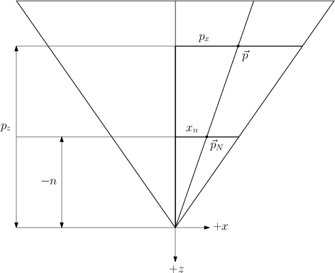
Our goal is to reconstruct the view-space point \(\vec{p} = \begin{bmatrix}p\_x & p\_y & p\_z\end{bmatrix}^T\).
\(p\_z\) can be computed straight away from the camera’s far plane and the depth buffer. The depth buffer stores the value:
\[d = \frac{-p_z}{f}\]
rearranging:
\[p_z = -d \, f\]
To compute \(p\_x\) and \(p\_y\), let \(\vec{p}\_N = \begin{bmatrix}x\_N & y\_N & -n\end{bmatrix}^T\) be the projection of \(\vec{p}\) onto the camera’s near plane. From the figure, we can see that similar triangles give us the relation:
\[\frac{p\_x}{p\_z} = \frac{x\_N}{-n}\]
Solving for \(p\_x\) yields:
\[p\_x = \frac{p\_z \; x\_N}{-n}\]
The case for \(p\_y\) is similar (figure omitted):
\[\frac{p\_y}{p\_z} = \frac{y\_N}{-n} \; \Leftrightarrow \; p\_y = \frac{p\_z \; y\_N}{-n}\]
This deals with \(\vec{p}\). Deriving \(\vec{p}\_{N}\) is relatively straightforward with the aid of the following figure:
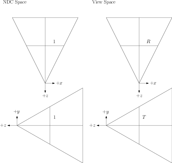
Note that in NDC space, the fragment’s coordinates \(\vec{p}\_{ndc}\) fall in the range \([-1,1]\). In view space, the \(x\) and \(y\) coordinates of \(\vec{p}\_{N}\) fall in the range \([-R,R]\) and \([-T,T]\), respectively, where R and T are the view frustum’s right and top values. Here we assume that the view frustum is symmetrical: the left value is \(-R\) and the bottom value is \(-T\). To obtain \(\vec{p}\_{N}\), then, simply scale \(\vec{p}\_{ndc}\) by the frustum’s right and top values:
\[\vec{p}\_{N} = \vec{p}\_{ndc} \, \begin{bmatrix}R & T\end{bmatrix}^T\]
If you are building the camera’s projection matrix by specifying the view frustum’s dimensions directly, as in a call to glFrustum, then you are done, since \(R\) and \(T\) are known. If, however, you are building the projection matrix by specifying the camera’s vertical field of view angle, aspect ratio and near and far planes, as in a call to gluPerspective, then you need to derive these values from the ones given.
To find \(R\) and \(T\) in this latter case, consider the following two figures of a view frustum seen from the top and side, respectively, showing the frustum’s near and projection planes as well as the different quantities associated with them – the frustum’s right value \(R\), top \(T\), near \(n\), distance to projection plane \(d\), and aspect ratio \(r\):
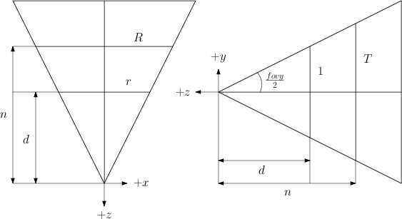
The projection plane here is completely arbitrary. We choose one with a convenient height of \(2\) (\(1\) from the center to the top) to simplify the calculations.
Applying right triangles once again on the right figure gives us:
\[\frac{T}{n} = \frac{1}{d} \Leftrightarrow T = \frac{n}{d}\]
The left figure gives us:
\[\frac{R}{n} = \frac{r}{d} \Leftrightarrow R = \frac{rn}{d} = rT\]
The distance to the projection plane can be solved using trigonometry:
\[tan \left( \frac{fovy}{2} \right) = \frac{1}{d} \Leftrightarrow d = cot \left( \frac{fovy}{2} \right)\]
Finally, we can simplify the expression for \(T\) by subtituting \(d\) into the equation:
\[\begin{align} T &= \frac{n}{d} \\\\ &= \frac{n}{cot \left( \frac{fovy}{2} \right)} \\\\ &= n \, tan \left( \frac{fovy}{2} \right) \end{align}\]
CPU Code
float T = n * tan(0.5*fovy); // fovy must be in radians
float R = r*T;
Shader Code
uniform vec2 RightTop; // vec2(R,T), R and T computed as shown above
uniform float Near;
uniform float Far;

vec3 unproject (vec2 tex, float d)
{
    vec2 ndc = tex*2.0 - 1.0;
    vec2 pnear = ndc * RightTop;
    float pz = -d*Far;
    return vec3(-pz*pnear.x / Near, -pz*pnear.y / Near, pz);
}
Method 2: Unprojection Using the Projection Matrix Inverse
Another method to unproject a point from texture space back into view space is by using the inverse of the projection matrix. Let’s first revisit the OpenGL pipeline involved in mapping a point from view space to texture space.
Pipeline Overview: From View to Texture Space
A point \(\vec{p}\) in view space is transformed to texture space by applying the following transformations:
Projection: multiply \([\vec{p},1]\) by the projection matrix to obtain point \(\vec{p}\_{clip}\) in clip space.
Perspective division: divide \(\vec{p}\_{clip}\) by \(p\_{clip}^w = -p\_z\) to obtain point \(\vec{p}\_{ndc}\) in normalised device coordinates.
Normalisation: map \(\vec{p}\_{ndc}\) from NDC space to texture space (from \([-1,1]^2\) to \([0,1]^2\), discarding \(z\) and \(w\)) by defining \(\vec{p}\_{tex} = \frac{\vec{p}\_{ndc}}{2} + \frac{1}{2}\).
By texture space, we mean the space of normalised texture coordinates – texture coordinates lying in the \([0,1]^2\) range. In the usual pipeline, a point \(\vec{p}\_{ndc}\) in NDC space is mapped to the viewport by applying a viewport matrix. In our case, however, this transformation is unnecessary. Instead, we map points from NDC space to texure space so that we can then use the resulting coordinates to fetch the depth from a depth buffer.
We now revisit the mathematics of projection in more detail, so that we can later do the steps in reverse and unproject a point.
Step 1: Projection
A perspective projection matrix is given by:
\[P = \begin{bmatrix} \frac{c}{r} & 0 & 0 & 0 \\\\ 0 & c & 0 & 0 \\\\ 0 & 0 & \frac{f+n}{n-f} & \frac{2fn}{n-f} \\\\ 0 & 0 & -1 & 0 \end{bmatrix}\]
where:
- \(c = cot\left(\frac{\mbox{fovy}}{2}\right)\)
- fovy = vertical field of view angle
- r = aspect ratio
- n = near plane
- f = far plane
A point \(\vec{p}\) is transformed from view space to clip space by multiplying the point by the projection matrix:
\[ \vec{p}\_{clip} = P \, \vec{p} = \begin{bmatrix} \frac{c}{r} & 0 & 0 & 0 \\\\ 0 & c & 0 & 0 \\\\ 0 & 0 & \frac{f+n}{n-f} & \frac{2fn}{n-f} \\\\ 0 & 0 & -1 & 0 \end{bmatrix} \begin{bmatrix}p\_x \\\\ p\_y \\\\ p\_z \\\\ 1\end{bmatrix} = \begin{bmatrix}\frac{c}{r}p\_x \\\\ cp\_y \\\\ Ap\_z + B \\\\ -p\_z\end{bmatrix} \]
where:
\[\begin{align} A &= \frac{f+n}{n-f} \\\\ \\\\ B &= \frac{2fn}{n-f} \end{align}\]
In clip space, a point’s \(x\), \(y\) and \(z\) coordinates lie in the range \([-w,w]\).
Step 2: Perspective division
The resulting point \(\vec{p}\_{clip}\) is mapped from clip space to NDC space by performing perspective division, dividing \(\vec{p}\_{clip}\) by \(p\_{clip}^w = -p\_z\):
\[\begin{align} \vec{p}\_{ndc} &= \frac{\vec{p}\_{clip}}{p\_{clip}^w} \\\\ &= \frac{\vec{p}\_{clip}}{-p\_z} \\\\ &= \begin{bmatrix}-\frac{c}{rz}p\_x & -\frac{c}{z}p\_y & -A - \frac{B}{p\_z} & 1\end{bmatrix}^T \end{align}\]
In NDC space, a point’s \(x\), \(y\) and \(z\) coordinates lie in the range \([-1,1]\).
Step 3: Normalisation
Finally, the point is mapped from NDC space to texture space by applying a simple scaling and translation, discarding the point’s \(z\) and \(w\) components in the process:
\[\vec{p}\_{tex} = \frac{\vec{p}\_{ndc}}{2} + \frac{1}{2}\]
In texture space, a point’s \(x\), \(y\) and \(z\) coordinates lie in the range \([0,1]\).
Unprojection
To unproject a point from texture space to view space using the inverse projection matrix, we perform the following three steps:
- Map input fragment from texture space to NDC space.
- Apply inverse projection matrix to obtain ray passing through point to be reconstructed.
- Scale ray to obtain the actual point.
Step 1: Texture space to NDC space
Given \(\vec{p}\_{tex}\), transform the point to NDC space:
\[\vec{p}\_{ndc} = 2\vec{p}\_{tex} - 1\]
From the review section above, we have that \(\vec{p}\_{ndc}\) in homogeneous coordinates is given by:
\[\vec{p}\_{ndc} = \begin{bmatrix}-\frac{c}{rz}p\_x & -\frac{c}{z}p\_y & -A - \frac{B}{p\_z} & 1\end{bmatrix}^T\]
where:
- \(c = cot\left(\frac{\mbox{fovy}}{2}\right)\)
- \(r\) = aspect ratio
- \(A = \frac{f+n}{n-f}\)
- \(B = \frac{2fn}{n-f}\)
Therefore, the mapping of \(\vec{p}\_{tex}\) to \(\vec{p}\_{ndc}\) is:
\[\vec{p}\_{ndc} = 2\vec{p}\_{tex} - 1 = \begin{bmatrix}-\frac{c}{rz}p\_x & -\frac{c}{z}p\_y\end{bmatrix}^T\]
The \(z\) and \(w\) components of \(\vec{p}\_{ndc}\) are unknown at this point, since all the work we have done here is in 2D.
Step 2: Unproject the NDC point to obtain the ray through the view-space point
Next, obtain the ray passing through the origin (camera position in view space) and the view space point to be reconstructed by applying the inverse of the projection matrix.
The inverse projection matrix is given by:
\[P^{-1} = \begin{bmatrix} \frac{r}{c} & 0 & 0 & 0 \\\\ 0 & \frac{1}{c} & 0 & 0 \\\\ 0 & 0 & 0 & -1 \\\\ 0 & 0 & \frac{n-f}{2fn} & \frac{f+n}{2fn} \end{bmatrix}\]
This can be verified by checking that \(PP^{-1} = I\) using the definition of \(P\) in the previous sections.
Augment the 2D point \(\vec{p}\_{ndc}\) by setting \(z=1\) and \(w=1\) and multiply the result by the inverse projection matrix \(P^{-1}\):
\[\begin{align} \vec{p}\_{ray} &= P^{-1} \begin{bmatrix}p^{ndc}\_x \\\\ p^{ndc}\_y \\\\ 1 \\\\ 1\end{bmatrix} \\\\ \\\\ &= \begin{bmatrix} \frac{r}{c} & 0 & 0 & 0 \\\\ 0 & \frac{1}{c} & 0 & 0 \\\\ 0 & 0 & 0 & -1 \\\\ 0 & 0 & \frac{n-f}{2fn} & \frac{f+n}{2fn} \end{bmatrix} \begin{bmatrix}-\frac{c}{rz}p\_x \\\\ -\frac{c}{z}p\_y \\\\ 1 \\\\ 1\end{bmatrix} \\\\ \\\\ &= \begin{bmatrix}-\frac{p\_x}{p\_z} \\\\ -\frac{p\_y}{p\_z} \\\\ -1 \\\\ w\end{bmatrix} \end{align}\]
The value of \(w\) is irrelevant for our purposes, so we omit its definition. Note that the result is only a scaling away from the desired value.
Step 3: Scale the ray to obtain the reconstructed point
Finally, scale the ray by \(d f\) to obtain the reconstructed point \(\vec{p}\) (the \(w\) component of \(\vec{p}\_{ray}\) is discarded):
\[\begin{align} d \; f \; \vec{p}\_{ray} &= \frac{-p\_z}{f} \; f \; \begin{bmatrix}-\frac{p\_x}{p\_z} & -\frac{p\_y}{p\_z} & -1\end{bmatrix}^T \\\\ \\\\ &= -p\_z \begin{bmatrix}-\frac{p\_x}{p\_z} & -\frac{p\_y}{p\_z} & -1\end{bmatrix}^T \\\\ \\\\ &= \begin{bmatrix}p\_x & p\_y & p\_z\end{bmatrix}^T \\\\ \\\\ &= \vec{p} \end{align}\]
Shader Code
uniform mat4 IProjection; // inverse projection matrix
uniform float f; // camera far plane

vec3 unproject (vec2 ptex, float d)
{
    vec2 pndc = ptex*2.0 - 1.0;
    vec3 pray = (IProjection * vec4(pndc, 1.0, 1.0)).xyz;
    return d*f*pray;
}